Hydrofoils of the USSR. Hydrofoil boat "Raketa": description, technical characteristics. Water transport
The concept of hydrofoils, which made it possible to dramatically increase the speed of ships, was proposed back in the 19th century. Since then, this design, embodied in thousands of ships, has come a long way and is now widely used in shipbuilding.
To be meticulous, we are talking about more than a century. Back in 1869, Parisian Emmanuel Denis Farcot received a patent with the formula: “Attaching inclined planes or wedge-shaped elements to the sides and bottom of a vessel, which, when the vessel moves forward, will lift it in the water and thus reduce drag.” In the years that followed, many patents were issued regarding various methods of lifting a vessel (wholly or partially) above the water in order to increase its speed or improve its performance on waves. The Comte de Lambert, a Russian citizen living in Versailles, applied for the patent in 1891. He attached several independently adjustable wings (lifting planes) along the sides of the ship, which were supposed to lift the ship above the water as speed increased. However, the very location of these primitive wings, in principle, did not make it possible to completely lift the ship above the surface of the water.
 "Raketa" - the first Soviet passenger ship
But the real history of the hydrofoil begins with Italian engineer Enrico Forlanini. He began working on the hydrofoil in 1898, and a series of model tests allowed him to derive mathematical principles. Based on the formulas, he began designing and building a full-scale vessel. Forlanini's designs were distinguished by a “stepped” arrangement of wings. Experiments with models showed that lift was proportional to the square of the speed - thus, as speed increased, less wing area was required. The “stepped” scheme was invented precisely in order to ensure automatic reduction in area. The experimental vessel weighed about 1,200 kg and was powered by a 60-horsepower engine that drove two counter-rotating propellers. The design speed of the vessel was 90 km/h, but during tests on Lake Maggiore in Italy in 1906, a speed of 68 km/h was achieved.

Early experiments with hydrofoils brought the greatest fame to an American living in Canada. It was Alexander Graham Bell. Along with Frederick W. (Casey) Baldwin and Philip L. Rhodes, he designed and built several hydrofoils, including the HD-4, powered by twin Liberty engines. On September 9, 1919, this ship set an official speed record, showing 114 km/h. Later, to improve the driving performance of the HD-4, many changes were made to the design, but this record remained officially unsurpassed.
The initial stage of the history of hydrofoils would be incomplete without paying tribute to the genius of Baron Hans von Schertel. Experiments of “Baron” (as his friends called him) with hydrofoils began in 1927. The fact that hydrofoils have evolved from an unreliable, unstable exotic toy capable of running only “on smooth water” into modern safe, efficient, high-speed means of transportation is largely due to von Schertel.

Meanwhile, interest in submersible craft had reawakened in Canada, and a 15-meter, five-ton boat based on Baldwin's latest designs was built on Lake Massawippi in Quebec. After several demonstration tests in fairly rough weather, the ship was transported to the Naval Research Institute, where it received the official name R-100. However, the unofficial name - "Massawippi" - was used much more often. Experiments with the R-100 were considered successful, and the Canadian government decided to finance the construction of another experimental vessel by Saunders-Roe in England. The R-103, with a displacement of 17 tons, had an aluminum hull (the R-100 was all wood), stacked wings and struts made of sheet aluminum, riveted to aluminum ribs and stringers (previously these elements were monolithic). The propulsion unit was organized in a fundamentally new way - the transmission shafts were connected at right angles through bevel gears, the stern tube, like in an outboard motor, went vertically down, and at its end there was a fairing with two screws - at the back and at the front. This complex design is radically different from the simple long and downward sloping shaft of the R-100. Two 12-cylinder Rolls Royce Griffon gasoline engines with a power of 1,500 hp were installed on board.
 Experimental boat of the founder of the hydrofoil concept, Enrico Forlanini. The wings were arranged in a “stack” (steps), and this made it possible to solve the problem of reducing the wing area with increasing speed in order to maintain a constant lift force. During testing on Lake Maggiore, the boat reached 68 km/h.
Then different times came, and the attention of the Canadian military focused on the fight against submarines. The role assigned to hydrofoil ships in these strategic plans required maximum mobility and versatility. A very cost-effective alternative to developing powerful long-range sonars that would be installed on large ships involved deploying a large number of low-power devices. In 1964, the hull of the new vessel BRAS D'OR was laid down, but on November 5, 1966, during construction work, a devastating fire occurred in the main engine room, which almost led to the termination of the entire program. And yet, despite all the delays and additional financial expenses, a new ship with the index FHE-400 and the same name BRAS D’OR was launched in 1967. Subsequently, this ship was used in tests and experiments, and also participated in naval parades.
 Hydrofoils can be divided into two general classes - partially submerged and fully submerged foils. The partially submerged wings are designed so that their tips penetrate the water-air interface during cruising mode. The struts connecting the wings to the hull of the vessel must be of sufficient length so that when moving at design speeds, the hull does not touch the water at all. As the speed increases, the lift force caused by the flow of incoming water around the underwater part of the wing increases; as a result, the ship rises somewhat, and, accordingly, the area of the submerged part of the wing decreases. This system is self-stabilizing: at any speed, the ship will rise exactly enough to ensure that the lifting force of the wing is equal to the weight of the entire ship.
In Russia, unlike the United States and the entire Western world in general, many thousands of hydrofoils were widely used in regular navigation on many rivers, canals and lakes. This is easy to understand if you consider that in a huge country with a general shortage of cars and roads, there are 150,000 rivers and 250,000 lakes. Krasnoye Sormovo in Gorky is one of the oldest shipyards in the Soviet Union. At this shipyard, in addition to a variety of displacement ships for the river fleet, many passenger hydrofoil ships were also built, and the variety of models had no analogues throughout the world. The father of Soviet hydrofoil boats was Rostislav Alekseev, who had been developing such systems since the early 1940s.
 Fully submerged hydrofoils are below the surface of the water. In this configuration, the hydrofoil system lacks the ability to self-stabilize. In response to changing conditions - ship speed, weight, waves - it is necessary to change the angle of attack of the wings and their lift. The main and invaluable advantage of a system with fully submerged wings is the ability to practically eliminate the impact of waves on the vessel. This allows a relatively small hydrofoil to move at high speeds in rough seas without affecting the comfort of passengers and crew, and in military applications without interfering with the use of combat equipment.
The ships used the effect of a low-submerged hydrofoil (Alekseev effect). Alekseev's hydrofoil consists of two main horizontal load-bearing planes - one at the front and one at the rear. The toe-in dihedral angle is either small or absent, and the weight distribution is approximately equal between the front and rear planes. A submerged hydrofoil, rising to the surface, gradually loses lift, and at a depth approximately equal to the length of the wing chord, the lift approaches zero.

It is due to this effect that the submerged wing is not able to fully come to the surface. In this case, a relatively small hydroplaning (sliding along the surface of the water) fender liner is used to help with “coming out on the wing”, and also does not allow the ship to return to displacement mode. These fender liners are located in close proximity to the front struts and are mounted so that they touch the surface of the water while moving, while the main wings are submerged to approximately a depth equal to the length of their chord. This entire system was first tested on a small boat powered by a 77-horsepower car engine.
 Based on the arrangement of the wings, they distinguish between an aircraft pattern, a canard pattern, and a tandem pattern (from top to bottom). Vessels are usually classified as an aircraft (conventional) or canard configuration if 65% of the weight or more falls on the bow or stern props, respectively. If the weight is distributed relatively evenly, this configuration is commonly called a "tandem".
Based on Alekseev’s developments, a large number of commercial hydrofoil vessels were built in Russia: “Raketa”, “Strela”, “Sputnik”, “Meteor”, “Kometa”, “Cyclone”, “Burevestnik”, “Voskhod”... They were also built military vessels, including the largest ship of this class in the world - “Butterfly”, it was preceded by “Bee”, “Turya” and “Locust”.
Hydrofoil principle
The essence of the concept is to lift the ship's hull out of the water and maintain it in this position in a dynamic mode, using planes called hydrofoils. As a result, it is possible to reduce the influence of waves and reduce energy consumption when moving at high speeds, often unattainable in normal (displacement) mode. The price you pay is increased draft at low speeds and stability problems. For ships with fully submerged wings, which almost completely “isolate” the ship’s hull from the influence of waves, but lack self-stabilization, an “autopilot” is required that monitors the position of the ship and corrects the lift of the wings by changing the angle of attack and deflecting the flaps.
Western Europe also did not stand aside. Gustoverft in Holland, Westermoen in Norway, Vosper Thornycroft in Great Britain are actively engaged in the development and construction of hydrofoils. But the most successful commercial projects developed and built in Western Europe are, of course, the works of the Italian Rodriquez Centieri Navali. Among its many products, it would be worth noting the RHS series of commercial vessels. Over the years, the vessels of this series grew in size and ventured into those waters where their wings, in principle designed to glide across the surface, were subjected to such loads that are not found in rivers, lakes and coastal lagoons. To create acceptable conditions for passengers, the Rodriquez company has developed a “Seakeeping Augmentation System” (SAS), which, as practice has shown, is very successful in combating vertical, pitching and roll in fairly strong waves.
 The Boeing Jetfoil had water-jet propulsion, fully submerged wings, a cruising speed of 45 knots in fairly high waves, and at the same time provided decent comfort for passengers.
In the early 1950s, the New York shipbuilding firm Gibbs & Cox joined forces with a group of specialists from the US Navy to create a universal hydrofoil prototype. The apparatus was built by the Bath Iron Works and named BIW. It was a boat 6 m long, one and a half meters wide and with a displacement of 0.8 tons, with a 22-horsepower outboard motor. BIW was very useful for testing various hydrofoil layouts, control systems, and various sensors. The most important result of this work was the basis for the development of an electro-hydraulic autopilot, as well as the decision to build a new vessel of this series - SEA LEGS (Sailor's Gait). The electronic autopilot, containing 160 radio tubes, was developed by Draper Laboratory in collaboration with the Massachusetts Institute of Technology. In 1957, SEA LEGS made its maiden voyage, demonstrating excellent seaworthiness in high waves at speeds of up to 27 knots.
 The fastest ferry in the world. The hybrid vessel with a forward hydrofoil Superfoil 40, built by the Almaz Marine Plant, has a cruising speed of more than 100 km/h.
This success inspired shipbuilders, and the American Navy began seriously working on experimental hydrofoils. These were Little Squirt, Hydrodynamic Test System (HTS), Foil Research Experimental Supercavitating Hydrofoil (FRESH-1). Several experimental vehicles were built by Boeing and Grumman/Lockheed Shipbuilding - High Point (PCH-1), Flagstaff (PGH-1), Tucumcari (PGH-2) and Plainview (AGEH-1). From the 57-ton Flagstaff to the 320-ton Plainview, the craft clearly demonstrated the capabilities and potential applications of hydrofoils in military operations. As a result, the Boeing Marine Systems division built the PHM (Patrol Hydrofoil Missile Ship) patrol vessel specifically for the US Navy. According to NATO plans, it was planned to build 26 such ships, but Germany and Italy refused to participate in this project, so that from 1977 to 1982, only six ships, named after constellations, entered service: PHM-1 PEGASUS (“Pegasus”), PHM -2 HERCULES (“Hercules”), PHM-3 TAURUS (“Taurus”), PHM-4 AQUILA (“Eagle”), PHM-5 ARIES (“Aries”) and PHM-6 GEMINI (“Gemini”).
Hybrids
Vessels, the design of which simultaneously uses two or more methods of maintaining on the water (or above the water) in most modes, are usually called hybrid. They use hydrofoils to generate lift, complementing conventional buoyancy.
1. Hydrofoils with a small waterline area. This is a hybrid of the hydrofoil principle and the SWATH (small waterline area ships) developments that were carried out in the 1970s and 1980s at the US Surface Warfare Research Center. The vessel consists of two hulls: one completely submerged hull with a completely recessed fender system, and above this another hull, supported completely above the water by a thin and long longitudinal strut. At low speed, buoyancy is provided by the displacement of the lower hull, the strut and a small segment of the upper hull. As speed increases, the dynamic lift of the wings lifts the upper hull above the water, and the waterline area (the horizontal cross-section of the thin strut) becomes extremely small. In this mode, the lower hull and submerged part of the strut provide 70% of the total buoyancy (due to displacement), and the wing system provides the remaining 30%. In the 1990s, the US Navy funded an attempt to build a demonstrator called QUEST. Maritime Applied Physics Corporation in Baltimore designed, built, launched and successfully tested the nine-metre, 12-ton vessel. QUEST had a speed of 35 knots in almost two-meter waves. More recently, Rodriquez developed the Aliswath, which uses a similar principle. It is reported that this large vessel - it will be a car and passenger ferry - should be launched as early as 2007.
2. Hydrofoil catamaran. Much of the work on the hydrofoil-assisted catamaran concept was done by Dr. Hopp, a naval engineer at the University of Stellenbosch in South Africa. This hybrid is a catamaran with completely asymmetrical hulls, between which a hydrofoil is located. In English, such catamarans are called Hydrofoil Supported Catamaran, and are designated by the abbreviation HYSUCAT. Variations of this concept are often used in the construction of passenger ferries (like the Foilcat).
3. Planing hulls/integrated wings. This configuration was proposed by Navatek - it was they who developed and tested various configurations of planing hulls with wings in different combinations. Since 1996, successful demonstrations of this principle have been carried out on prototype Midfoil and Waverider vessels. Using computer fluid dynamics calculation programs and involving specialists from the University of California at Long Beach, Navatek took a new step in the development of planing hulls - an integrated wing (Blended Wing Body, BWB). The main purpose of BWB is to improve the seaworthiness and speed of existing or designed types of vessels.
4. Vessels with a front fender. The stern of such a vessel seems to “drag” through the water. A typical example of this approach is the Superfoil 40 catamaran, built by the Almaz Marine Plant according to a project by the St. Petersburg branch of the British company MTD (Marine Technology Development) and commissioned by the Estonian company Linda Lines Express. This ship is the fastest passenger ferry in the world, it is capable of reaching a speed of 55 knots (over 100 km/h), so the trip on the Tallinn-Helsinki route takes only 50 minutes.
But instead of modernizing these ships, the leadership of the American fleet decided to write them off in 1993. Later, some of these boats were sold under the hammer, and some were scrapped. Since then and to this day, the US Navy has been doing nothing but making plans, doing “paper developments” and going through designs for ships with a displacement from 615 to 2400 tons: Corvette Escort, DBH, PCM, Grumman HYD-2...
During the 1990s, the commercial direction developed in its own way, absorbing new design solutions from Japan, Norway, Sweden, Russia, Italy and the USA. One of the new Russian developments is the Cyclone vessel with a cruising speed of 42 knots (78 km/h) - an enlarged double-deck version of the Comet, designed for 250 passengers and equipped with an electronic automatic control system. An even newer Russian design, the Olympia, is the pinnacle in the development of large vessels capable of operating routes almost on the open sea.

Boeing's Jetfoil model went into production in the mid-1970s and has served well in many parts of the world. At that time, this was the height of perfection for commercial hydrofoils. In 1989, Kawasaki acquired a license from Boeing and launched its own production of the Jetfoil model. Many devices from this series are still in service in the vicinity of Hong Kong. There, in Japan, Mitsubishi designed and built several passenger hydrofoils called Rainbow.
In Sweden and Norway, devices with a catamaran hull and wings mounted on relatively short struts, such as Westamarin's Foilcat 2900, were operated on Baltic lines.
In 1994, the Italian company Rodriquez released the Foilmaster, another example of the careful layout of a pusher propeller with the appropriate wing profile for maximum performance, but with the traditional layout of stern propellers driven by a long inclined shaft.
At the end of the 19th century, the first attempts to build hydrofoil ships began. The first country that decided to develop the speed of water transport is France. It was there that de Lambert, a designer of Russian origin, proposed creating a ship with wings under water. He suggested that when using hydrofoils or propellers, some kind of air cushion would be created under the ship. Due to it, water resistance will be much less and ships equipped with hydrofoils will be able to reach much higher speeds. But the project was not implemented, since the power of steam engines was simply not enough.
History of the development of hydrofoil boats
At the beginning of the last century, the Italian aircraft designer E. Forlanini was nevertheless able to realize Laber’s idea of hydrofoils. And this happened thanks to the emergence and use of new, powerful gasoline engines. Multi-tiered wings and 75 hp motor. With. on gasoline, did their job, the ship was able not only to stand on its wings, but also reached a record speed of 39 knots at that time.
A little later, the American inventor improved the design, increasing the ship's speed to a record 70 knots. Later, already in 1930, an engineer from Germany invented wings of a more ergonomic shape, reminiscent of the Latin letter V. The new wing shape allowed the ship to stay on the water, even in strong waves, with a speed of up to 40 knots.

Russia also became one of the countries that were engaged in similar developments and in 1957, a famous Soviet shipbuilder developed a series of large boats codenamed:
- Rocket;
- Meteor;
- Comet.
The ships were very popular in the foreign market, they were purchased by countries such as the USA, Great Britain, as well as countries of the Middle East. Widespread use of hydrofoil boats served for military purposes, for reconnaissance of territory and patrolling maritime borders.

Soviet and Russian military hydrofoil boats
The Navy had about 80 hydrofoil boats. The following types were distinguished:
- Small anti-submarine ships. In terms of technical components, the boat consisted of an engine with two turbines with a capacity of 20 thousand hp. pp., middle side rudder, thruster, located in the bow of the ship and two rotary columns located at the stern. The main advantages were high speed and a radio station that operated over thousands of kilometers. The ship weighed 475 tons and was 49 meters long and 10 meters wide. The speed was 47 knots, with autonomy up to 7 days. The ships were armed with two or four tube torpedo tubes, and the ammunition load was 8 missiles.
- Boats of project 133 “Antares”. Any boat from this series had such technical characteristics as a displacement of 221 tons, a length of 40 meters and a width of 8 meters. The maximum speed was 60 knots, with a range of 410 miles. The power plants consisted of two gas turbine engines of the M-70 series, with a capacity of 10 thousand hp. With. each. The armament included a 76-mm artillery system with 152 rounds of ammunition and a 30-mm anti-aircraft gun with 152 rounds of ammunition. In addition, most of the ships had 6 BB-1 class depth charges and an MRG-1 grenade launcher and one bomb releaser. It was considered a great advantage that the ship was capable of reaching speeds of up to 40 knots in a force five storm.

At one time, all developed countries managed to take part in the construction of hydrofoil boats, but Soviet ships are considered the best. During the Soviet era, about 1,300 hydrofoil ships were built. The main disadvantages of the ships were considered to be low fuel efficiency and the impossibility of approaching an unequipped shore.
In 1990, the last hydrofoil boat was put out of service. Over the entire history of that ship, it was controlled by 4 captains - V.M. Dolgikh and E.V. Vanyukhin - captains of the third rank, V.E. Kuzmichev and N.A. Goncharov - lieutenant captain. Subsequently, it was transferred to the OFI for disarmament and cut into metal.
“Burevestnik”, “Sputnik”, “Comet” and “Meteor” - the names of these Soviet ships gave rise to romantic thoughts about flight. Although we were talking only about a river trip. However, it’s hard to say, a trip on a hydrofoil is also swimming, but there is something of flying in it. These ships, which in general terms were called rockets and could reach speeds of 150 km/h (carrying up to 300 passengers), were the same symbol of the USSR of the 60s - 80s, like the real space rockets that roamed the Bolshoi Theater outer space.
The severe economic crisis (if not an industrial disaster) of the 90s led to a sharp reduction in the number of ships of this class. Now let's remember the brief history of these unusual ships.
The principle of movement of these ships was twofold. At low speed, such a ship moves like an ordinary ship, that is, due to the buoyant force of water (hello to Archimedes). But when it develops high speed, due to the hydrofoils these ships have, a lifting force arises, which lifts the ship above the water. That is, a hydrofoil is both a ship and, as it were, an airplane at the same time. He just flies low.

Perhaps the most elegant high-speed hydrofoil was the so-called. gas turbine ship "Burevestnik". It was developed by the Central Design Bureau of the SPK R. Alekseev in the city of Gorky and, with a length of 42 meters, could reach a design speed of 150 km/h (although there is no data that the ship ever reached such a speed).

The first (and only) experimental vessel, Burevestnik, was built in 1964.

It was operated by the Volga Shipping Company on the Volga along the route Kuibyshev - Ulyanovsk - Kazan - Gorky.

What made this vessel especially impressive were the two aircraft gas turbine engines on its sides (such engines were used on the IL-18 aircraft).

In such a ship, travel should indeed resemble flight.

The captain's cabin was particularly elegant, the design of which was reminiscent of the design of futuristic American limousines of the 50s (the photo below, however, is not the cabin of the Burevestnik, but about the same).

Unfortunately, having worked until the end of the 70s, the unique 42-meter “Burevestnik” was written off due to wear and tear, and remained in a single copy. The immediate reason for the decommissioning was an accident in 1974, when the Burevestnik collided with a tug, severely damaging one side and the gas turbine engine. After this, it was restored, as they say, “somehow” and after some time its further operation was considered unprofitable.
Another type of hydrofoil was the Meteor.

The Meteors were smaller than the Burevestnik (34 meters in length) and not as fast (no more than 100 km/h). Meteors were produced from 1961 to 1991 and, in addition to the USSR, were also supplied to the countries of the socialist camp.

A total of four hundred motor ships of this series were built.

Unlike the aircraft engines of the Burevestnik, the Meteors flew using diesel engines driving propellers typical of ships.

Vessel control panel:

But the most famous hydrofoil is probably the Raketa.

“Rocket” was first presented in Moscow in 1957 at the International Student Youth Festival.

The leader of the USSR Nikita Khrushchev himself then expressed himself in the spirit that, they say, it’s enough to swim along rivers in rusty bathtubs, it’s time to travel in style.

However, at that time only the first experimental “Rocket” was running along the Moscow River, and after the festival it was sent for trial operation to the Volgna on the Gorky-Kazan line. The ship covered a distance of 420 km in 7 hours. An ordinary ship would travel the same route for 30 hours. As a result, the experiment was considered successful and “Rocket” went into production.

Another famous Soviet ship is the Comet.

"Comet" was a naval version of "Meteor". This 1984 photo shows two Comets in the seaport of Odessa:

"Comet" was developed in 1961. They were mass-produced from 1964 to 1981 at the Feodosia shipyard "More". A total of 86 Komets were built (including 34 for export).
One of the “Comets” that has survived to this day in a bright design:

By the beginning of the 70s, “Rockets” and “Meteors” were already considered obsolete ships and the “Voskhod” was developed to replace them.

The first ship of the series was built in 1973. A total of 150 Voskhods were built, some of which were exported (China, Canada, Austria, Hungary, the Netherlands, etc.). In the 90s, production of Voskhods was stopped.
Sunrise in the Netherlands:

Among other types of hydrofoils, it is worth remembering the Sputnik.

It was truly a monster. At the time of construction of the first Sputnik ship (October 1961), it was the world's largest passenger hydrofoil ship. Its length was 47 meters, and its passenger capacity was 300 people!

“Sputnik” was first operated on the Gorky - Tolyatti line, but then, due to its low landing, it was transferred to the lower reaches of the Volga on the Kuibyshev - Kazan line. But he spent only three months on this line. On one of the voyages, the ship encountered a sinkhole, after which it stood in a ship repair yard for several years. At first they wanted to cut it into scrap metal, but then they decided to install it on the Togliatti embankment. “Sputnik” was placed next to the river station, where it housed a cafe of the same name, which with its appearance continues to delight (or frighten) the residents of Avtograd (proof).

The marine version of Sputnik was called “Whirlwind” and was intended for sailing in waves up to 8 points.

It is also worth remembering the ship “Chaika”, which was created in a single copy and took 70 passengers on board, but reached a speed of up to 100 km/h

Another rare one we can’t help but mention is “Typhoon”...


...and "Swallow"

A story about Soviet hydrofoils would be incomplete without a story about a man who devoted his life to creating these ships.

Rostislav Evgenievich Alekseev (1916-1980) - Soviet shipbuilder, creator of hydrofoils, ekranoplanes and ekranoplanes. Yacht designer, winner of all-Union competitions, master of sports of the USSR.
He came to the idea of hydrofoils while working during the war (1942) to create combat boats. His boats did not have time to take part in the war, but in 1951 Alekseev was awarded the Stalin Prize of the second degree for the development and creation of hydrofoils. It was his team that created “Rocket” in the 50s, and then, starting in 1961, almost every year a new project: “Meteor”, “Comet”, “Sputnik”, “Burevestnik”, “Voskhod”. In the 60s, Rostislav Evgenievich Alekseev began work on creating the so-called. "Ekranoplans" - ships for the airborne forces, which were supposed to hover above the water at a height of several meters. In January 1980, during testing of a passenger ground-propelled aircraft, which was to be put into operation for the 1980 Olympics, Alekseev was seriously injured. He died from these injuries on February 9, 1980. After his death, the idea of ekranoplanes was never returned to.
And now I offer some more photos of these incredibly beautiful hydrofoils:
Built in 1979, Comet-44 is today operated in Turkey:


Project "Olympia"

Project "Katran"

Double-decker monster "Cyclone"

Ship cemetery near Perm.


Bar "Meteor" in Kanev (Ukraine)

Red Meteor in China

But even today these ships of the 60s designs look quite futuristic.

Having risen above the surface of the water, these ships rush past at the speed of an express train; At the same time, they provide their passengers with the same comfort as on a jet airliner. Such vessels are also associated with the idea of a liner by having wings attached to their bottom using thin struts, located under the surface of the water. These are the most characteristic features of hydrofoils. Currently, ships of this type, with a high degree of safety and reliability, transport millions of passengers in all parts of the world along sea bays, lakes and rivers, as well as in coastal shipping. In the Soviet Union alone, the leading country for ships of this class, hydrofoil ships of various types annually transported more than 20 million passengers on regular lines. Hydrofoils received new development in the last years of the 20th century. And today, debates continue about the prospects for the development of hydrofoil vessels, and these discussions are even more heated than before, since other ways to increase the speed of sea vessels have been outlined in technology. The very idea of creating a hydrofoil vessel arose more than 100 years ago. The first patent for a hydrofoil boat was issued back in 1891. In 1905, a small hydrofoil boat reached an unusually high speed for those times - 70 km/h. Between 1927 and 1944, and then in the 1950s, research work on hydrofoils was carried out at the Rosslau shipyard. Experimental hydrofoil vessels weighing from 2.8 to 80 tons were built there. The hydrofoil system created by designer Schertel in Rosslau has found application in many ship projects, primarily on ships of the Swiss company Supramar in Lucerne. A new stage in the development of hydrofoils began in 1935, when Soviet scientists Keldysh and Lavrentiev proposed a complete hydrofoil theory. Under the leadership of the talented designer Alekseev, the development of hydrofoils continued so successfully that the Soviet Union was able to begin their mass production in the 50s. Now the serial construction of hydrofoil ships is already carried out at shipyards in the USA, Japan, Italy, Norway and other countries. Many hundreds of such vessels are already in operation. They swim mainly along rivers and reservoirs, as well as along the coasts of the Black and Baltic seas. Hundreds of hydrofoils are also in operation off the coast of Scandinavia, in the Mediterranean and Caribbean seas, and off the Asian and Australian coasts.
The vessel can carry 100 passengers at a speed of 40 knots with wave heights of up to 2-3 m. The length of the vessel is 31.4 m, width 5.6 m. The vessel is equipped with a gas turbine power plant with a capacity of 2570 hp. With.
The Soviet ship "Kometa" accommodates 100 passengers. This vessel reaches a speed of 35 knots with a cruising range of 500 km. Waves up to 1.5 m high do not interfere with the vessel. An even larger hydrofoil vessel floats on the Black Sea resort lines - the 300-seat Whirlwind. This 117-ton vessel can reach a speed of 43 knots in calm water. A completely new, modern modification of the hydrofoil vessel is the Soviet Typhoon. In exceptionally comfortable conditions, it carries 100 passengers at a speed of 40 knots with wind force up to 5 on the Beaufort scale. The electronic control system keeps the vessel in a horizontal position at all times, regardless of sea conditions. This is, of course, a great achievement, helping to maintain the well-being of passengers during sea voyages. The project of the Soviet 70-knot vessel “Dolphin” is known, which was supposed to be the fastest hydrofoil in the world. Just like some of its predecessors, it is supposed to be equipped with water-jet propulsion and a gas turbine. The American hydrofoil Jetfoil is also of interest. This 112-ton vessel, designed for 250 passengers, reaches a speed of 40 knots using water jet propulsion. Electronically controlled hydrofoils make it possible to maintain a stable hull position despite the waves. If the storm intensifies, the wings are raised and the vessel continues its voyage in displacement mode with the help of auxiliary propulsors. With the wings raised, in particular, maneuvers are performed when entering, mooring and leaving the port.

American hydrofoil type "Jetfoil"
This double-decker ship carries 250 passengers. The length of the vessel is 27.4 m, width 9.5 m. A gas turbine power plant with a power of 4850 kW gives the vessel a speed of 40 knots using water jet propulsion.
Currently, the largest civilian hydrofoil vessel has a 165-ton vessel of the RT-150 type, built in Norway under license from the Swiss company Supramar. The RT-150 has seating for 150 passengers and a car deck for transporting eight medium-sized passenger cars. This ferry-operated vessel has a cruising range of 250 miles and an operating speed of 36.5 knots, which is much faster than any conventional ferry. All hydrofoils built so far or currently under construction are intended only for transporting passengers or for resort voyages. With frequent traffic on the line, a passenger capacity of more than 100-250 people is not required. Such ships are not suitable for transporting goods. A vessel of the RT-150 type, for example, has a net carrying capacity of no more than 23 tons, which is less than 15% of the total weight of the vessel. It should be added that the cruising range of the mentioned vessel is only 400-600 km, since with a longer range the mass of fuel reserves will completely “eat up” the payload capacity. The hydrofoil RT-150 has a power plant with a power of about 5000 kW. It is easy to calculate that for every ton of the vessel’s mass there is a power of 30.3 kW, i.e. 15-20 times more than that of a traditional ferry.

Car-passenger hydrofoil ferry RT-150
Will the development of hydrofoils stop at the current level?

The answer to this question can be confidently: no. There are already hydrofoil warships weighing 320 tons with a speed of 70 knots. On the drawing boards of designers you can find designs for ships weighing 400-500 tons. In the Soviet Union, a 400-ton hydrofoil vessel with a speed of 47-52 knots was developed. Among other numerous projects, it is worth mentioning a 500-ton hydrofoil vessel with a speed of 100 knots and a power plant power of 44 thousand kW. The payload of this vessel is 100 tons. For a long time it was believed that the limit of the mass of a hydrofoil vessel, due to physical laws, is 1000 tons. This is due to the belief that the destructive effect of cavitation on hydrofoils limits the speed of winged ships to 65-70 knots. For such a speed, a 1000-ton hydrofoil vessel was designed with a power plant power of 39 thousand kW and a possible payload of about 400 tons. Such a vessel allows us to think about transoceanic flights. New research has shown the technical feasibility of building a hydrofoil vessel weighing 2500-3000 tons, which could transport containers, cars and other valuable cargo across the ocean at a speed of 150 knots. High racks will raise the hull of this vessel so high above the surface of the water that no waves will be afraid of it. Of course, the appearance of such large and very fast hydrofoils can only be expected in the distant future. For technical and economic reasons, in the coming years, attention will primarily be focused on hydrofoils weighing no more than 200 tons.
The possibility of increasing the size of the vessels in question very much depends on the adopted hydrofoil design. This is due to the following main provisions. The principle of movement of a hydrofoil vessel is that profiled wings located under its bottom and rigidly connected to the vessel, installed at a certain angle, during the forward movement of the vessel create dynamic lifting forces, which, at a sufficiently high speed, lift the vessel’s hull above the water surface and support it is in this state when moving. This is the same principle as airplanes, with the difference that water is about 800 times denser than air. But since the lifting force of the wing is directly proportional to the density of the medium, the necessary dynamic forces to support the vessel are created with relatively small areas of the hydrofoils. In addition to fulfilling its main purpose - providing the necessary lifting force, hydrofoils must also perform other functions. All seaworthiness, which in conventional displacement vessels is determined by the shape of the hull, in hydrofoil vessels is ensured by the hydrofoil design - the type of their design and position along the length of the vessel. Such qualities include longitudinal and lateral stability, course stability and seaworthiness, limited draft (for river vessels), etc. That is why hydrofoils are a defining element of the design of the vessels in question. Hydrofoil systems can be classified both by their location and by the principles of ensuring the stability of the movement of ships and their stability. Based on the first feature, three main schemes can be distinguished:
The usual arrangement in which the area of the bow hydrofoils is much greater than the area of the stern hydrofoils, as a result of which the bow wings bear the main load. This scheme is adopted on all Supramar ships;
(1)
An arrangement of the car nag d type, in which the area of the aft hydrofoils is much greater than the area of the bow ones. This arrangement is used on some American hydrofoil warships; (2)

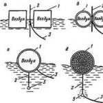
A large number of different solutions are known regarding the principles of ensuring motion stability and stability. Trapezoidal, V-shaped and arched hydrofoils crossing the water surface are self-stabilizing (Fig. 1). If a ship equipped with such wings, due to the action of some external forces, such as wind or waves, falls deeper into the water or rolls on board, then at this point an additional area of the wings enters the water and an additional lifting force arises, which restores the position. Although such hydrofoils are simple in design, sailing on such vessels is not very pleasant for passengers, since when sailing at high speed in waves, changes in the magnitude of lifting forces are associated with periodic shocks. Such fender systems are not suitable for large boats. Foil systems that cross the surface of the water and also have the property of self-stabilization include systems of the “shelf” or “ladder” type, where the hydrofoils are installed in two or more rows in height, one above the other (Fig. 2). When heeling or trimming, additional wings that were previously above the water enter the water, which leads to an increase in lifting force and to the restoration of the vessel’s position. Such systems, adopted for Soviet hydrofoil ships, are very simple in design and allow the operation of winged ships with shallow draft on rivers. Strong waves, however, are contraindicated for such wing systems. It is highly doubtful that the use of such wing systems will provide any advantages in terms of reducing draft compared to other types of wing systems. Quite the contrary. By the way, the overwhelming majority of Soviet hydrofoil ships use low-submerged hydrofoils, which for some reason fell out of the authors’ field of vision, the lift of which is adjusted automatically, decreasing when approaching the surface of the water (the lift increases as the wing moves away from the surface).

The most suitable for swimming on waves are fully submerged wings with a variable angle of attack (Fig. 3). The angle of attack is changed using automatically operating actuators based on signals from mechanical or acoustic sensors of the water surface level in front of the wing. Thanks to this, the lifting force of the wings is automatically adjusted, maintaining an almost constant value. The hull of a vessel equipped with such a wing system moves without any shocks at an almost constant distance from the wave crests. In this case, however, it is necessary that the hydrofoils do not become exposed when passing the bottom (trough) of the wave, and that the struts attaching the hydrofoils to the hull are of such length that the crests (tops) of the waves do not touch the hull of the vessel. But since the height of the props must be in a certain proportion to the length of the vessel, the maximum wave height that a hydrofoil can overcome depends on the size of the vessel. The largest of modern hydrofoil vessels can be operated at wave heights of no more than 3-3.5 m. On larger, promising vessels, only fully submerged hydrofoils with a variable angle of attack will be installed. The larger the vessel, the longer the props can be and the better seaworthiness it will be. When the speed increases above a certain limit, cavitation begins to affect the hydrofoils. The pressure on the suction (upper) surface of the wing drops to such an extent that the water there boils and steam bubbles form. These bubbles are then carried by the flow to an area of higher pressure, where they collapse, causing severe damage to the upper part of the hydrofoil. Until now, it has not yet been possible to create hydrofoils suitable for speeds above 70 knots.
Further increases in speed and the associated increase in the size of hydrofoils largely depend on whether the harmful effects of cavitation can be overcome. The speed and mass of a hydrofoil vessel are directly related: it is advisable to increase the hydrodynamic support forces created by the hydrofoils by increasing the speed, and not by increasing the wing area, since the lift of the wing is proportional to the square of the speed and only the first power of the hydrofoil area. Thus, as the size of a hydrofoil vessel increases, its speed should also increase. Here a difficult-to-solve problem of main engines arises. The power of a hydrofoil ship's power plant is approximately proportional to the product of the ship's mass and its speed.
A 100 ton hydrofoil at 40 kt requires approximately 2800 kW. For a vessel 10 times heavier, with a speed of 65 knots, from 45 to 60 thousand kW will be required. A promising 3,000-ton hydrofoil vessel with a speed of about 150 knots will have a main engine power that is unlikely to be less than 300 thousand kW. So, it is absolutely clear that forecasts for further technical progress of hydrofoil ships should be based only on achievements in the field of creating new types of wing profiles and heavy-duty engines. In the next 10-20 years, the development of hydrofoil ships will be characterized by the fact that ferry traffic and short-distance passenger transportation will increasingly be carried out by ships of this type, weighing 100-150 tons, and in some cases up to 400 tons. In this sense You shouldn't be overly optimistic. In the early 60s in the USA, for example, forecasts were made regarding the creation of 1000-ton transoceanic hydrofoil ships in our years. However, we are still very far from this.
Launched on the waters of Lake Maggiore, the boat with built-on “wings”, created by the Italian inventor, reached an unprecedented speed for 1906 - 68 km/h. The boat's engine had a power of only 60 horsepower and drove two propellers rotating in opposite directions.
Operating principle- these are devices included in the structure of the ship’s hull, made in the form of wings (hence the name). Their main purpose is to reduce friction and resistance of water, the ship's hull, and also reduce the vessel's draft.
The principle of operation of hydrofoils is similar to the wings of aircraft. At high speeds, due to the bending of the wing, the ship rises above the water. Only the wings and engines remain submerged. The optimal propulsion force of a vessel depends on its speed. Since the density of water is 800 times greater than the density of air, the wing area, as well as the speed of the ship, with the same buoyancy force as that of an airplane, will be 800 times less.
- Such vessels are capable of moving through water in two modes: In normal ship mode. Each type of hydrofoil has a design speed at which the buoyancy force lifts the ship's hull above the water (similar to the takeoff speed of an airplane). Before reaching this speed, the ship is immersed in water, in accordance with Archimedes' law
- . At the same time, the draft increases greatly, as the wings increase it. To solve this problem, folding wings and rising propellers are used. In hydrofoil mode. Reaching pushing speed, the ship rises above the water
, by reducing the friction force, the speed increases sharply, and the draft becomes minimal.
 There are two main types of hydrofoils:
 As the area of contact of such wings with water increases, the buoyancy force they create also increases. Thanks to this property, the vessel is more stable when waves occur. To improve the smooth movement of the ship in heavy seas, partially submerged wings can be equipped with automatically controlled flaps.Fully submerged (U-shaped) wing.
Control of the buoyancy force when the wing is completely immersed in water is carried out by changing the angle of attack (rotating the entire wing) or deflecting the flaps, which are located on the fixed wing, along the trailing edge. Regulation of the vessel's position above the water is provided by an automatic control system. The control computer monitors the position of the vessel and automatically balances it.
The control system must have a very high reliability coefficient, since if it fails, the U-wing vessel can capsize.

There are three types of hydrofoil configurations used in practice:
- The wing arrangement is similar to an aviation one (aircraft layout). In this position, the large wing (main) is located in front of the metacenter of the ship, and the smaller wing (secondary) is located behind the center of gravity. Wings of this type are used on small ships with a shallow draft.
- The wing arrangement is “canard”. This design involves placing a smaller wing in front of the main one (resembling the shape of a duck). They are used similarly to “aviation” ones.
- Tandem scheme. Tandem wings are equivalent to each other and are located in front and behind the metacenter of the vessel, at the same distance from it. A similar design is used in the design of large, seaworthy hydrofoil vessels.
Hydrofoil propulsion systems
To reach the glide path (that is, to achieve a speed sufficient to “stand up” on the wings), the ship must have a powerful engine. On ships with hydrofoils, internal combustion engines (diesel) and gas turbine units are used.
Water-jet and screw propulsors are used together with them. Large-tonnage ships are equipped with both types of propulsors, switching depending on the mode of movement of the ship; most often they are driven by gas turbine units.
 Features of wing movement in water
When a hydrofoil moves in water, a zone of low pressure forms on its upper surface. This contributes to the formation of air bubbles, this effect is called cavitation. When air bubbles collapse, they can damage the wing. An area of low pressure sufficient for bubbles to form occurs when the ship reaches a certain speed.
- Based on the occurrence of cavitation, hydrofoils are divided into two types: Non-cavitation wings.
- Their maximum speed is lower than the speed required for cavitation to occur. Supercavitating.
Wings for high-speed vessels. The wing profile is designed in such a way that cavitation bubbles collapse at a distance from the wing surface. In 1956 it was developed new type of wing profile , designed to become independent from cavitation. He is symmetrical wedge . When moving in a liquid, positive dynamic pressure arises on its faces. On its outer convex side the pressure decreases, and on its concave side it increases. In the high pressure region that occurs on the convex side of the curved wedge,, and at high angles of attack of the wing, the bends of the trailing edges delay the occurrence of cavitation.
Features of the use of hydrofoils
 The introduction of hydrofoils led to changes in the architecture of the ships using them. To reduce the aerodynamic drag of the hull, ships of this type have become streamlined. Due to the low load capacity, the main purpose of such ships was the transportation of passengers and excursions, their internal cabin layout corresponds to the airplane cabin.
Wheelhouse(captain's bridge) are located at the bow of the ship to improve visibility when passing winding rivers. Utility rooms are located between the passenger compartment and the engine room, thereby reducing engine noise (penetrating into the cabin) and increasing passenger comfort.
For ship design hydrofoils were developed new hull development techniques. Taking into account increased bending moment. In addition, the operating features require strong waves hitting the hull when the vessel is planing.
All these factors are determined by the design of the wing device, especially the nose one. As a result of the use of hydrofoils, developed under the guidance of Doctor of Technical Sciences, Professor N.V. Matthes, managed to reduce the dynamic loads on the body to 50 - 60%.
The hydrofoils and hull of the ship average 45–55% of its empty weight. That's why optimal materials lightweight and durable alloys are used to create gliders aluminum and stainless steel, for making wings. Currently, many small ships use wings made of fiberglass with reinforcement allowing to significantly reduce the weight of the vessel.
The technology for manufacturing hydrofoils is very expensive. Therefore, in some cases, designers resort to worsening hydrodynamic characteristics, reducing the cost of building a ship. For example, riveted body joints are replaced by welded joints. This makes the structure heavier, but greatly reduces the complexity and cost of the work.
Ways to control hydrofoils
The buoyancy force on a hydrofoil vessel is controlled by changing the angle of attack of the wing or by flaps. Currently, all control systems are automated. The operator performs only rough control - turning, decelerating and accelerating the vessel, and stabilization of the movement is provided by the central processor of the vessel control. Receiving information about the position of the vessel from sensors, it transmits signals to change the angle of attack of the wing or flap. Holding the vessel in the position specified by the operator. For gliders, only the fastest processors and sensors are used, since the time for signal transmission and processing at high speeds should be minimal.
We also recommend
 Localization of oil on the surface of water bodies
 Compassionate Living download fb2
 Quick start: adaptation of employees in the organization
 Characteristics for a manager from the place of work (sample) Sample characteristics for the head of the legal department of the award
 Focus group. insomar. marketing and market research When not to use a focus group
 Who appoints the school director Does the school director have the right to reduce lessons