Principles of construction of fuel supply systems and automation of aviation gas turbine engines. General information about automatic control systems for aviation gas turbine engines gas turbine engines planning system
Aviation: Encyclopedia. - M.: Great Russian Encyclopedia. Editor-in-Chief G.P. Svishchev. 1994 .
See what "" is in other dictionaries:
gas turbine engine automatic control system Encyclopedia "Aviation"
gas turbine engine automatic control system- automatic control system of a gas turbine engine a set of devices that automatically ensure the execution, with the required accuracy, of selected control programs for the gas turbine engine of an aircraft at steady and transient... ... Encyclopedia "Aviation"
system- 4.48 system: A combination of interacting elements organized to achieve one or more specified goals. Note 1 A system can be considered as a product or the services it provides. Note 2 In practice... ... Dictionary-reference book of terms of normative and technical documentation
SAU GTE- automatic control system for gas turbine engine
Getting Things Done is often translated into Russian as “putting things in order,” although it would be more accurate to “bring things to the end.” Agree, it is more important not to stuff tasks into lists, but to complete them. This is exactly why you need to make lists, determine priorities and come up with a schedule.
And why is this necessary?
Working according to the principles of GTD, it will be easier for you to manage your affairs. After all, the main advantage of this technique is that information about all your tasks is concentrated in one place so that you can move from one task to another without hesitation.What is the difference between a GTD and a task list?
In the list, we usually record only the most important things, and do not write down less significant, small tasks. And in vain. They scroll through your head, distract you from your work, and your effectiveness drops. One of the main principles of GTD is to capture absolutely everything. This way you can unload your brain and use all its resources for work.Is this system really right for me?
GTD is relevant for people of different professions, ages and social status. David Allen, who formulated the principles of the system, conducted courses for ISS astronauts, rock musicians, and executives of large companies.As David Allen told Lifehacker, the system can be equally effective or equally useless for both a teenager and the CEO of a large company. You need to have a certain mindset, love to organize and plan.
Okay, so what exactly should you do?
There are no strict rules in the GTD system. But there are basic operating principles:- Collect information and record everything. Write down tasks, ideas, and recurring tasks in a notepad or app. At the same time, the list should always be at your fingertips so that you can’t say: “I’ll add this later.” Even the smallest and most insignificant task should be written down if you are not doing it right now.
- Write explanations. There should be no tasks like “Prepare for vacation.” Break down big tasks into specific, manageable actions (submit such and such documents to the visa center, buy a towel and sunglasses, download maps to your phone). With a typical task list, we spend more time deciphering than completing. And yes, if you can delegate, delegate.
- Set your priorities. For each item in the list, provide a specific date and deadline. Add reminders if necessary. Essentially, this is working with both a list and a calendar. At this stage, you should have confidence that you will definitely not forget anything.
- Update your lists. To-do lists quickly become outdated: something loses its relevance, something is postponed to the future. The system should work for you. So make sure you always have a list of specific actions so you can get started without delay.
- Take action. When everything is organized, you can begin to implement your plans. Select a case from the desired category, see what specific actions are required of you, and work. This way you can implement big projects.
Should everything be written down in one list?
No, it’s better to make several, but store them in one place. For example, keep several lists for each work project, lists of household chores, lists to study, lists of ideas and possible projects in the future - whatever your imagination allows.Are there any special tools?
Apps and web services include Wunderlist, Trello, Any.do, MyLifeOrganized, any note-taker or a regular file in Google Docs. If you are used to taking notes on paper, you can use it.There are fans of the file system. One common folder is created on the desktop, in which there are several thematic ones, and each contains the corresponding lists and necessary materials.
In general, choose what is convenient for you.
The main requirement: the tool should always be at your fingertips so that you can transfer the task from your head to paper or to an application. For example, when your boss comes to you and assigns you a new task, and at that time you are working on something else.
How to get more value from GTD?
Any productivity system will not work if applied blindly. To get the most out of it, customize it for yourself, and then everything will work out.And yes, no system can do everything for you, so don’t get too carried away with making lists, don’t forget to take action. GTD is a tool that helps you get rid of stress and not forget anything. But how you manage your time is up to you.
Principles of construction of fuel supply systems and automation of aviation gas turbine engines
Tutorial
UDC 62-50(075)
General information is provided on the composition and operation of fuel supply systems for aircraft gas turbine engines. Regulatory programs for twin-shaft gas turbine engines are described.
Information about the automatic control system of the NK-86 engine is presented.
schematic diagram of a hydromechanical self-propelled gun;
electronic analog self-propelled control system of the engine.
A description of the design diagram of the engine self-propelled control system is given.
The textbook is intended for students of specialties
Introduction
General information about the engine self-propelled guns
Schematic diagram of a hydromechanical self-propelled gun
Electronic analog engine control system
Composition and operation of the gas turbine engine fuel system
Gas turbine regulation programs
Automatic engine control system NK-86
Design diagram of the engine self-propelled gun
Fuel supply systems for modern gas turbine engines
Introduction
The operation of a gas turbine engine (GTE) is controlled by changing fuel consumption. At the same time, unlike an engine for ground use, control of an aviation gas turbine engine must be carried out taking into account the flight conditions of the aircraft, wide changes in environmental parameters (altitude and air temperature), the peculiarities of the operating processes in the engine and many other factors.
Therefore, the fuel supply system of a modern aviation gas turbine engine includes a number of automatic devices that help the aircraft crew ensure efficient and safe use of the engine’s capabilities at various stages of the flight.
Aggregate composition of the gas turbine engine fuel supply system
The engine fuel system consists of three main parts:
Fuel conditioning system (I);
Fuel supply system at engine start (II);
Fuel dosing system in the main engine operating modes (III).
The fuel conditioning system is designed to impart specified physical and mechanical parameters to the fuel. These options include:
temperature;
degree of cleaning from mechanical contaminants;
specified pressure and flow.
Fuel from the aircraft system enters the centrifugal booster pump (1), driven by an automatic electric motor. The booster pump is designed to overcome the resistance of the units with fuel and supply it to the main fuel pump with excess pressure for cavitation-free operation.
Fuel heaters (2), (3).
Despite thorough cleaning of the fuel from any water present at fuel and lubricant stations, it is not possible to completely remove water from the fuel. The presence of water leads to clogging (freezing) of fuel filters and their failure. Therefore, before the filter, the fuel must be heated to positive temperatures. The fuel is heated by extracting heat from the engine oil system (in the fuel-oil heater (2)), and in case of insufficient heating of the fuel due to hot air due to the engine compressor in the fuel-air heater (3).
The heated fuel flows to the fine fuel filter (4). The filter provides fuel purification with a filtration fineness of 16 microns. In case of clogging, the filter is equipped with a bypass valve, which opens at a pressure drop of 0.075 +0.01 MPa. At the same time, a signal indicating that the filter is clogged appears in the cockpit.
The main fuel pump (5) supplies fuel with a pressure of up to 10 MPa and a flow rate of up to 12,000 kg/hour. The power of the main fuel pump is several tens of kilowatts. Therefore, the fuel pump is driven into rotation by the gas turbine engine rotor through a system of power take-off gears. If a non-regulated feed gear pump is used as a pump, a safety valve (9) is provided in the pump design.
The fuel dosing system at engine start (II) consists of the following units:
additional fine fuel filter (6);
dosing device for the starting system (7) with a hydromechanical drive;
fuel shut-off valve (8);
fuel injectors of the starting system (16).
Dosing of the flow rate of the fuel supplied at startup is carried out by changing the area of the flow section of the automatic starter (7) at the command of a hydromechanical drive or according to a local time program, and on modern engines according to intra-engine parameters (rotor speed, rate of change of frequency dn/ dt, on the degree of air compression in the compressor P k * / P H and others).
The change in fuel consumption at engine operating modes is carried out by the main fuel system (III).
Fuel from the pump is supplied to the main metering device (11) with a hydromechanical drive.
Since the main device in the fuel supply system of a gas turbine engine is a metering device with a hydromechanical drive. Let's look at his work in more detail.
The hydromechanical drive changes the fuel flow area, being the actuator of the units and components of the automatic engine control system. It is connected (Fig. 2) with:
rotor rotation regulator and carries out crew commands to change engine operating modes from idle to takeoff mode;
a system for adjusting fuel consumption during throttle response and gas release, taking into account the aircraft's flight altitude;
system for adjusting fuel consumption when the pressure and temperature of the air entering the engine changes ( R N * , T N * );
electronic engine control system (ECM) to limit the maximum permissible engine rotor speed and gas temperature at the turbine inlet;
limiter of the maximum compression ratio of the fan.

Fig.2. Scheme of interaction of the dosing device with the units and components of the automatic engine control system.
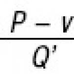
The dosing device operates by changing the flow area. In this case, fuel consumption changes in accordance with the following relationship:
 , (1)
, (1)
where: μ is the flow coefficient determined by the geometry of the flow part of the dosing device;
F D.u– flow area;
R us– pressure developed by the pump;
R f
ρ – fuel density.
Formula (1) shows that the fuel consumption supplied to the injectors is determined by the flow area of the metering device and the pressure drop ( R us -R f). This difference depends on variable pressure values behind the pump and in front of the nozzles. In order to eliminate ambiguity in fuel consumption, the system is equipped with a special device - a constant differential fuel pressure valve (10) on the metering device. This valve senses the fuel pressure downstream of the pump. R us and pressure at the outlet of the dosing device (pressure in front of the nozzles). When the difference between these pressures changes, valve (10) changes the bypass of part of the fuel from the pump output to its input. At the same time, fuel consumption through the metering device is proportional to the area of the flow section, and if this area does not change, it ensures a constant value of fuel consumption for any pressure deviations R us And R f. This ensures accurate dosing of fuel consumption in all operating modes of the engine.
The shut-off (fire) valve (12) together with the valve (8) ensures that the engine is turned off.
The flow meter (13) of the fuel entering the gas turbine engine makes it possible to determine the value of instantaneous fuel consumption, which is one of the most important diagnostic parameters for assessing the technical condition of the engine. In addition, using a flow meter, the total amount of fuel entering the engine during the flight is determined and the remaining fuel on board the aircraft is determined. Turbine flow sensors are used as flow meters.
The fuel distributor along the circuits of the working injectors (15) is a two-channel three-position distributor. The need for such a unit in the fuel system is explained as follows. Fuel consumption when changing modes from idle to takeoff increases 10 times or more. This change in the required flow rate is ensured by an increase in the pressure drop across the nozzles in accordance with the formula:
 , (2)
, (2)
where: μ is the flow coefficient determined by the geometry of the flow part of the nozzles;
F F– flow area of the injectors;
R f– fuel pressure in front of the engine injectors;
R KS– pressure in the engine combustion chamber;
ρ – fuel density.
Formula (2) shows that for a tenfold increase in fuel consumption, increase it no less than a hundred times. To reduce the fuel pressure at the pump outlet, modern gas turbine engines are equipped with two injector circuits. In this case, at low operating modes, fuel enters the engine through injectors 1 th circuit, and then through nozzles 1 th and 2 th contours. Thanks to this, fuel flow into the engine is ensured at significantly lower pressure. Graphically, the operation of the fuel distributor along the contours of the fuel injectors is illustrated as in Fig. 3.
The dotted lines in the figure represent flow characteristics 1 th and 2 th injector circuits, and the solid line is the fuel flow entering the engine through two circuits simultaneously.

Rice. 3 Operation of the fuel distributor along the fuel injector circuits
At low operating modes, fuel enters the engine through injectors 1 th contour. When the pressure drop reaches ( ΔР open) additional fuel begins to flow through injectors 2 th circuit and then the fuel flow into the engine is supplied simultaneously through both circuits. In this case, the fuel consumption is equal to ( G T 1+2 K) the amount of expenses for the circuits ( G T 1 TO + G T 2K) and is provided at significantly lower fuel pressure.
METHODOLOGICAL INSTRUCTIONS
to perform laboratory work
“Composition and principle of operation of systems,
servicing GTD VK-1 and GTD 3F"
by academic discipline
"Ship power plants,
main and auxiliary"
for students of direction 6.0922 – Electromechanics
all forms of education
Sevastopol
UDC 629.12.03
Guidelines to perform laboratory work No. 2 “Composition and principle of operation of systems servicing gas turbine engines VK-1 and gas turbine engines 3F” in the discipline “Ship power plants, main and auxiliary” for students of direction 6.0922 “Electromechanics”, specialty 7.0922.01 “Electrical systems and transport complexes” means" of all forms of education / Comp. G.V. Gorobets - Sevastopol: SevNTU Publishing House, 2012. – 14 p.
The purpose of the guidelines is to assist students in preparing for laboratory work to study the structure, design and operation of turbogenerators of ship power plants.
The guidelines were approved at a meeting of the Department of Power Installations of Marine Vessels and Structures, Minutes No. 6 dated January 25, 2011.
Reviewer:
Kharchenko A.A., Ph.D. technical sciences, associate professor department EMSS
Approved by the educational and methodological center of SevNTU as methodological instructions.
CONTENT
| 1. General information…..……………………………………………………. | |
| 1.1. SEU fuel systems……………………………………………. | |
| 1.2. SEU oil systems………………………………….………….. | |
| 1.3. SEU cooling systems……………………………..…………. | |
| 1.4. GTE venting system…………………………………………. | |
| 1.5. Gas turbine engine launch and control system.…………………………………. | |
| 2. Laboratory work “Composition and principle of operation of systems servicing gas turbine engines VK-1, gas turbine engines-3F”……….......................... .......... | |
| 2.1. Goal of the work…………………………………………………………… | |
| 2.2. Brief description of the VK-1 engine and its elements…………………. | |
| 2.3. Composition of systems ensuring the operation of the VK-1 gas turbine engine………………... | |
| 2.4. Description of the GTE 3-F engine systems………………………………. | |
| 2.5. Preparation of the report…………………………………………………………….. | |
| 2.6. Control questions……………………………………………….. | |
GENERAL INFORMATION
A power plant system is a set of specialized pipelines with mechanisms, apparatus, devices and instruments designed to perform certain functions that ensure the normal operation of the power plant. Sometimes it is called a mechanical system (as opposed to a general ship system).
In general, the system includes pipelines (pipes, fittings, fittings, connections, compensators), apparatus (cleaning, heat exchange, various purposes), devices, containers (tanks, tanks, cylinders, boxes) and instruments (pressure gauges, vacuum gauges, thermometers, flow meters).
Cleaning devices include coarse and fine filters, filtration units, centrifugal and static separators, separators. Heat exchangers are divided according to purpose into heaters, coolers, evaporators and condensers.
Devices for various purposes include noise silencers at the inlet and outlet of engines and mechanisms, spark arresters for exhaust gases of marine engines and homogenizers.
A given system may only include some of the equipment listed.
ECS systems are classified by purpose (and therefore by working environment): fuel, oil, water cooling (sea and fresh water), air-gas (air supply for fuel combustion, compressed air, gas exhaust, chimneys of ship boilers), condensate- nutritious and steam. A steam system, for example, includes a number of pipelines: main, exhaust and auxiliary steam, boiler blowing, sealing and suction of steam, etc. Systems of the same name may differ in composition if they are intended to serve different engines.
SEU fuel systems
Fuel systems are designed to receive, store, pump, clean, heat and supply fuel to engines and boilers, as well as to transfer fuel ashore or to other vessels.
Due to the wide range of functions performed, the fuel system is divided into a number of independent systems (pipelines). In addition, the power plant often uses several types of fuel and in this case, separate pipelines are provided for each type of fuel, for example diesel, heavy fuel, boiler fuel. All this complicates the system.
Gas turbine fuel system designed to perform the following functions:
Supplying fuel to the combustion chamber nozzles in all operating modes of the gas turbine engine;
Ensuring automatic start;
Maintaining the specified fuel consumption in the mode;
Changes in fuel supply in accordance with the specified operating mode;
Providing normal, emergency and emergency engine stops.
Many gas turbine engines have two parallel fuel systems: starting and main.
SEU oil systems
Lubrication systems are designed to receive, store, pump, clean and supply oil to places where the rubbing parts of mechanisms are cooled and lubricated, as well as to transfer it to other ships and to shore. Depending on the main purpose, oil pipelines are distinguished: receiving and pumping, circulating lubrication system, oil separation, drainage, oil heating. Circulating lubrication systems are divided, in turn, into pressure, gravity and pressure-gravity.
In addition to closed circulation systems, linear type systems are used, in which oil is supplied only to the objects of lubrication and is not returned back to the system (lubrication of the surfaces of internal combustion engine cylinders and compressors).
Oil system of gas turbine engine serves to lubricate turbomachinery bearings and gears and remove heat from them. Technical requirements for oil for marine gas turbine engines are established by GOSTs. For engine rolling bearings, low-viscosity, heat-stable oil is used, and for gears and gearbox bearings, oil with a kinematic viscosity (at 50 0 C) of 20...48 cSt. Oil consumption during gas turbine engine operation is (0.1…0.2)10 -3 kg/(kW×h).
SEU cooling systems
Designed to remove heat from various mechanisms, devices, instruments and working media in heat exchangers.
Cooling objects in the SDS are:
Cylinder liners and covers, exhaust manifolds and valves of main engines (MA) and diesel generators (DG), pistons and injectors of the main engine, and sometimes the diesel generator;
Working cylinders of air compressors;
Ship shafting bearings;
Circulating oil of main motor and diesel generators, main gear reducers;
Fresh water used as an intermediate coolant in the main generator and diesel generator;
Charge air main engine and diesel generator;
Air leaving the low pressure cylinder of air compressors during two-stage compression.
In the case of using main electric transmissions, the windings of propulsion electric motors and main diesel generators should be added to the cooling objects listed above.
The working media in the SDU are: sea and fresh water, oil, fuel and air.
GTE venting system
When the air pressure in the seal support system decreases (which is possible at low gas turbine engines), the oil will penetrate into the flow part and burn there. This can be detected by increased oil consumption. With an increase in air pressure in the sub-pod system, the passage of air into the oil cavities increases, which leads to an abundant formation of an oil-air mixture. The oil that enters the air separating centrifuges of the venting system contains 30...60% air. This leads to foaming of the oil and deterioration of the oil system. Contact of foamed oil on bearings (especially plain bearings) creates unfavorable conditions for the formation of the necessary oil wedge and impairs the heat transfer of cooled surfaces.
The venting system is designed to select the oil-air mixture from the oil cavities, separate the oil from the air and then return the oil to the system and the air to the atmosphere.
The system includes:
Pipelines connecting the oil cavities of bearings with the settling tank;
A settling container (tank), where oil droplets are released from the mixture and deposited on the walls. The drain tank of the oil system and the internal cavities of the inlet devices of the gas turbine engine compressor are used as a settling tank;
Oil separating separators (centrifuges or breathers) of a centrifugal or rotational operating principle, which complete the process of separating the oil-air mixture into its component parts. The breathers are driven from the turbocharger shaft through the gearbox and have an impeller that creates a vacuum at the suction. Thanks to this, the oil-air mixture enters the centrifuge housing, where oil droplets are thrown to the periphery and flow down the walls of the housing to the drain pipe. The air along the axis of the centrifuge is discharged into the atmosphere.
Centrifugal breathers have a number of disadvantages: the speed of oil passing through the rotor is too high to ensure the sedimentation of small particles; the need for additional drive and some others. Their insufficient efficiency causes environmental pollution and leads to irretrievable oil losses, and oil consumption (irretrievable losses) is one of the important operational characteristics of gas turbine engines.
To reduce irreversible oil losses by separating and returning it to the oil system, which is dictated by both environmental and resource-saving aspects, static (non-drive) jet breathers have begun to be used in gas turbine engines of the latest generations. The operating principle of such breathers is based on a physical process: the enlargement of oil droplets in the breathed air and their separation from the air. Oil losses are reduced by more than half; engine reliability increases; emissions of oil aerosol into the environment are reduced. The degree of purification in static prompters is 99.99%.
Advantages: high cleaning efficiency, high reliability, simple design.
GTE launch and control system
Starting systems can be electric, with a turbocharger starter, an air turbostarter, etc. Electric is most often used as the easiest to operate, with a high degree of automation, reliable and easy to maintain. The electric starting system includes:
Source of electrical energy (batteries or ship generators);
Software mechanism;
Actuators of automatic start systems;
Electric motor (starter);
A unit for supplying and igniting fuel in the combustion chamber (units can be combined into an autonomous starting system or be part of a combined gas turbine engine fuel system);
Devices for automatic control of parameters and protection of gas turbine engines during startup (ensure stable operation of compressors and prevent emergency situations by affecting the anti-surge devices of the compressor and the fuel supply to the combustion chamber);
Devices to ensure stable operation of the gas turbine engine during startup;
Control and launch panel.
2. Laboratory work
“Composition and PRINCIPLE OF OPERATION of systems,
servicing GTD VK-1 and GTD-3F"
Goal of the work
Acquiring practical knowledge by studying systems that service the operation of gas turbine engines. The work is performed on gas turbine engines VK-1 and gas turbine engines -3F.
INTRODUCTION
Over the sixty years of their development, gas turbine engines (GTEs) have become the main type of engines for modern civil aviation aircraft. Gas turbine engines are a classic example of a complex device, the parts of which operate for a long time under conditions of high temperatures and mechanical loads. Highly efficient and reliable operation of aviation gas turbine power plants of modern aircraft is impossible without the use of special automatic control systems (ACS). It is extremely important to monitor and manage engine operating parameters to ensure high reliability and long service life. Therefore, the choice of automatic engine control system plays a huge role.
Currently, aircraft are widely used in the world on which V generation engines are installed, equipped with the latest automatic control systems such as FADEC (Full Authority Digital Electronic Control). Hydromechanical self-propelled guns were installed on aircraft gas turbine engines of the first generations.
Hydromechanical systems have come a long way in development and improvement, ranging from the simplest, based on controlling the supply of fuel to the combustion chamber (CC) by opening/closing a shut-off valve (valve), to modern hydroelectronic ones, in which all the main control functions are performed using hydromechanical meters -decisive devices, and only to perform certain functions (limiting gas temperature, turbocharger rotor speed, etc.) electronic regulators are used. However, now this is not enough. In order to meet the high requirements for flight safety and efficiency, it is necessary to create fully electronic systems in which all control functions are performed by electronic means, and the actuators can be hydromechanical or pneumatic. Such self-propelled guns are capable of not only monitoring a large number of engine parameters, but also monitoring their trends, managing them, thereby, according to established programs, setting the engine to the appropriate operating modes, and interacting with aircraft systems to achieve maximum efficiency. The FADEC self-propelled gun belongs to such systems.
A serious study of the design and operation of automatic control systems for aviation gas turbine engines is a necessary condition for the correct assessment of the technical condition (diagnostics) of the control system and their individual elements, as well as for the safe operation of automatic control systems for aircraft gas turbine power plants in general.
GENERAL INFORMATION ABOUT AUTOMATIC CONTROL SYSTEMS FOR AVIATION GTE
Purpose of automatic control systems
gas turbine engine fuel management
The self-propelled gun is designed for (Fig. 1):
Controlling engine start and shutdown;
Engine operating mode control;
Ensuring stable operation of the compressor and combustion chamber (CC) of the engine in steady-state and transient modes;
Preventing engine parameters from exceeding the maximum permissible limits;
Ensuring information exchange with aircraft systems;
Integrated engine control as part of an aircraft power plant using commands from the aircraft control system;
Providing control over the serviceability of ACS elements;
Operational monitoring and diagnosing of the engine condition (with a combined automatic control system and control system);
Preparation and delivery of engine condition information to the registration system.
Providing control over engine starting and shutdown. At startup, the self-propelled gun performs the following functions:
Controls the fuel supply to the CS, the guide vane (VA), and air bypasses;
Controls the starting device and ignition units;
Protects the engine during surges, compressor breakdowns and turbine overheating;
Protects the starting device from exceeding the maximum speed.
Rice. 1.
The self-propelled control system ensures that the engine is turned off from any operating mode upon the pilot's command or automatically when limiting parameters are reached, and that the fuel supply to the main compressor is briefly interrupted in the event of loss of gas-dynamic stability of the compressor (GDU).
Engine operating mode control. Control is carried out according to the pilot's commands in accordance with specified control programs. The control action is the fuel consumption in the compressor station. During control, a given regulation parameter is maintained, taking into account the parameters of the air at the engine inlet and intra-engine parameters. In multi-coupled control systems, the geometry of the flow part can also be controlled to implement optimal and adaptive control in order to ensure maximum efficiency of the “CS - aircraft” complex.
Ensuring stable operation of the compressor and engine compressor station in steady-state and transient modes. For stable operation of the compressor and compressor, automatic program control of the fuel supply to the combustion chamber in transient modes, control of air bypass valves from the compressor or behind the compressor, control of the angle of installation of the rotary blades BHA and HA of the compressor are carried out. The control ensures the flow of the line of operating modes with a sufficient margin of gas-dynamic stability of the compressor (fan, booster stages, pressure pump and pressure build-up). To prevent exceeding the parameters in the event of loss of the compressor GDU, anti-surge and anti-stall systems are used.
Preventing engine parameters from exceeding the maximum permissible limits. The maximum permissible parameters are understood as the maximum possible engine parameters, limited by the conditions for fulfilling the throttle and altitude-speed characteristics. Long-term operation in modes with maximum permissible parameters should not lead to the destruction of engine parts. Depending on the engine design, the following are automatically limited:
Maximum permissible speed of engine rotors;
Maximum permissible air pressure behind the compressor;
Maximum gas temperature behind the turbine;
Maximum temperature of turbine blade material;
Minimum and maximum fuel consumption in the compressor station;
Maximum permissible rotation speed of the starting device turbine.
If the turbine spins up when its shaft breaks, the engine is automatically switched off with the maximum possible speed of the fuel cut-off valve in the combustion chamber. An electronic sensor can be used that detects exceeding the threshold rotation speed, or a mechanical device that detects the mutual circumferential displacement of the compressor and turbine shafts and determines the moment the shaft breaks to turn off the fuel supply. In this case, control devices can be electronic, electromechanical or mechanical.
The design of the ACS must provide for above-system means of protecting the engine from destruction when limiting parameters are reached in the event of failure of the main control channels of the ACS. A separate unit may be provided, which, when the maximum value for the above-system limitation of any of the parameters is reached, with maximum speed issues a command to cut off the fuel in the CS.
Information exchange with aircraft systems. Information exchange is carried out through serial and parallel information exchange channels.
Providing information to control, testing and adjustment equipment. To determine the serviceable condition of the electronic part of the ACS, troubleshooting, and operational adjustment of electronic units, the engine accessory kit contains a special control, testing and adjustment panel. The remote control is used for ground operations, and in some systems it is installed on board the aircraft. Information exchange is carried out between the ACS and the console via coded communication lines through a specially connected cable.
Integrated engine control as part of an aircraft control system using commands from the aircraft control system. In order to obtain maximum efficiency of the engine and the aircraft as a whole, the control of the engine and other control systems is integrated. Control systems are integrated on the basis of on-board digital computer systems integrated into the on-board complex control system. Integrated control is carried out by adjusting engine control programs from the control system, issuing engine parameters to control the air intake (AI). Upon a signal from the VZ self-propelled control system, commands are issued to set the engine mechanization elements to the position of increasing the reserves of the compressor gas turbine unit. To prevent disruptions in a controlled airborne aircraft when the flight mode changes, the engine mode is adjusted or fixed accordingly.
Monitoring the serviceability of ACS elements. In the electronic part of the engine ACS, the serviceability of the ACS elements is automatically monitored. If the ACS elements fail, information about the malfunctions is provided to the aircraft control system. The control programs and the structure of the electronic part of the ACS are being reconfigured to maintain its functionality.
Operational monitoring and diagnostics of engine condition. The ACS integrated with the control system additionally performs the following functions:
Reception of signals from engine and aircraft sensors and alarms, their filtering, processing and output to on-board display, registration and other aircraft systems, conversion of analog and discrete parameters;
Tolerance control of measured parameters;
Monitoring the engine thrust parameter during takeoff;
Monitoring the operation of compressor mechanization;
Monitoring the position of the elements of the reversing device on forward and reverse thrust;
Calculation and storage of information about engine operating hours;
Monitoring hourly consumption and oil level when refueling;
Monitoring the engine start time and run-down of the LPC and HPC rotors during shutdown;
Monitoring air intake systems and turbine cooling systems;
Vibration control of engine components;
Analysis of trends in changes in the main parameters of the engine at steady state.
In Fig. Figure 2 schematically shows the composition of the units of the automatic control system of the turbofan engine.
Given the currently achieved level of operational process parameters of aviation gas turbine engines, further improvement of the characteristics of power plants is associated with the search for new control methods, with the integration of self-propelled control systems into a unified aircraft and engine control system and their joint control depending on the mode and stage of flight. This approach becomes possible with the transition to electronic digital engine control systems such as FADEC (Full Authority Digital Electronic Control), i.e. to systems in which electronics control the engine at all stages and modes of flight (systems with full responsibility).
The advantages of a digital control system with full responsibility over a hydromechanical control system are obvious:
The FADEC system has two independent control channels, which significantly increases its reliability and eliminates the need for multiple redundancies and reduces its weight;

Rice. 2.
The FADEC system provides automatic start-up, operation in steady-state conditions, limitation of gas temperature and rotation speed, start-up after the combustion chamber goes out, anti-surge protection due to a short-term reduction in fuel supply, it operates on the basis of various types of data received from sensors;
The FADEC system is more flexible because... the number and nature of the functions it performs can be increased and changed by introducing new or adjusting existing management programs;
The FADEC system significantly reduces crew workloads and enables the use of widely used fly-by-wire aircraft control technology;
FADEC functions include engine health monitoring, fault diagnosis and maintenance information for the entire powertrain. Vibration, performance, temperature, fuel and oil system behavior are among the many operational aspects that can be monitored to ensure safety, effective life control and reduced maintenance costs;
The FADEC system provides registration of engine operating hours and damageability of its main components, ground and travel self-monitoring with storage of results in non-volatile memory;
For the FADEC system, there is no need for adjustments and checks of the engine after replacing any of its components.
The FADEC system also:
Controls traction in two modes: manual and automatic;
Controls fuel consumption;
Provides optimal operating conditions by controlling the air flow along the engine path and adjusting the gap behind the turbine engine blades;
Controls the oil temperature of the integrated drive-generator;
Ensures compliance with restrictions on the operation of the thrust reverser system on the ground.
In Fig. 3 clearly demonstrates the wide range of functions performed by the FADEC self-propelled guns.
In Russia, self-propelled guns of this type are being developed for modifications of AL-31F, PS-90A engines and a number of other products.
Rice. 3. Purpose of a digital engine control system with full responsibility